How to Connect the Xhorse XDNPBDGL Clamp with Wires and Start Using It with VVDI Key Tool Plus
 sales
How to Connect the Xhorse XDNPBDGL Clamp with Wires and Start Using It with KTP
The official Xhorse video shows the general BMW key-cloning procedure
But it does not clearly show how the wires are connected to the clamp or which cable is required.
To use the Xhorse XDNPBDGL BMW BDC2/BDC3/BCP/U Key Adapter Set with VVDI Key Tool Plus (KTP), you need the DB15 connection and the Xhorse MCU wire harness.
The complete connection is:
VVDI Key Tool Plus → DB15 connector/MCU cable → adapter terminals → clamp → original BMW key PCB
Official Xhorse operation video:
https://www.youtube.com/watch?v=ekv0uAZ5TKY
What You Need
- Xhorse VVDI Key Tool Plus;
- Xhorse XDNPBDGL BMW dedicated adapter set;
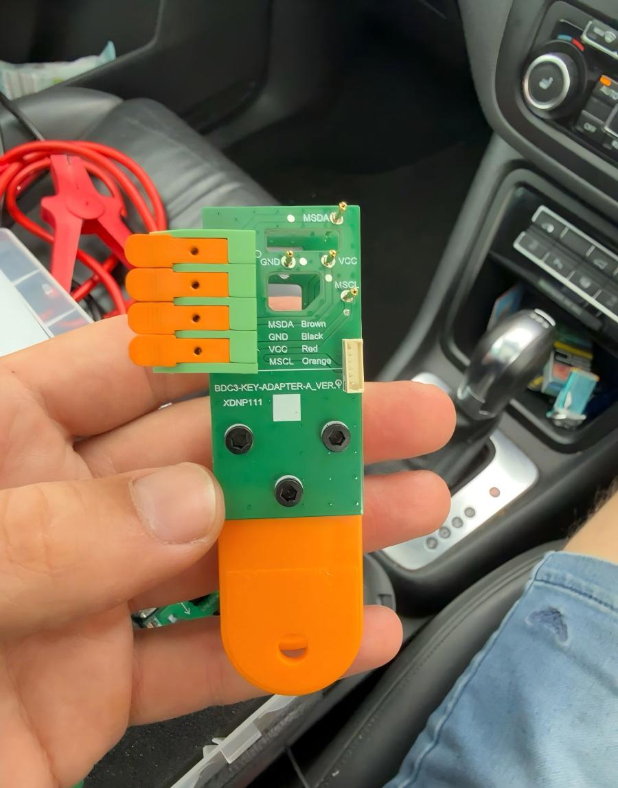
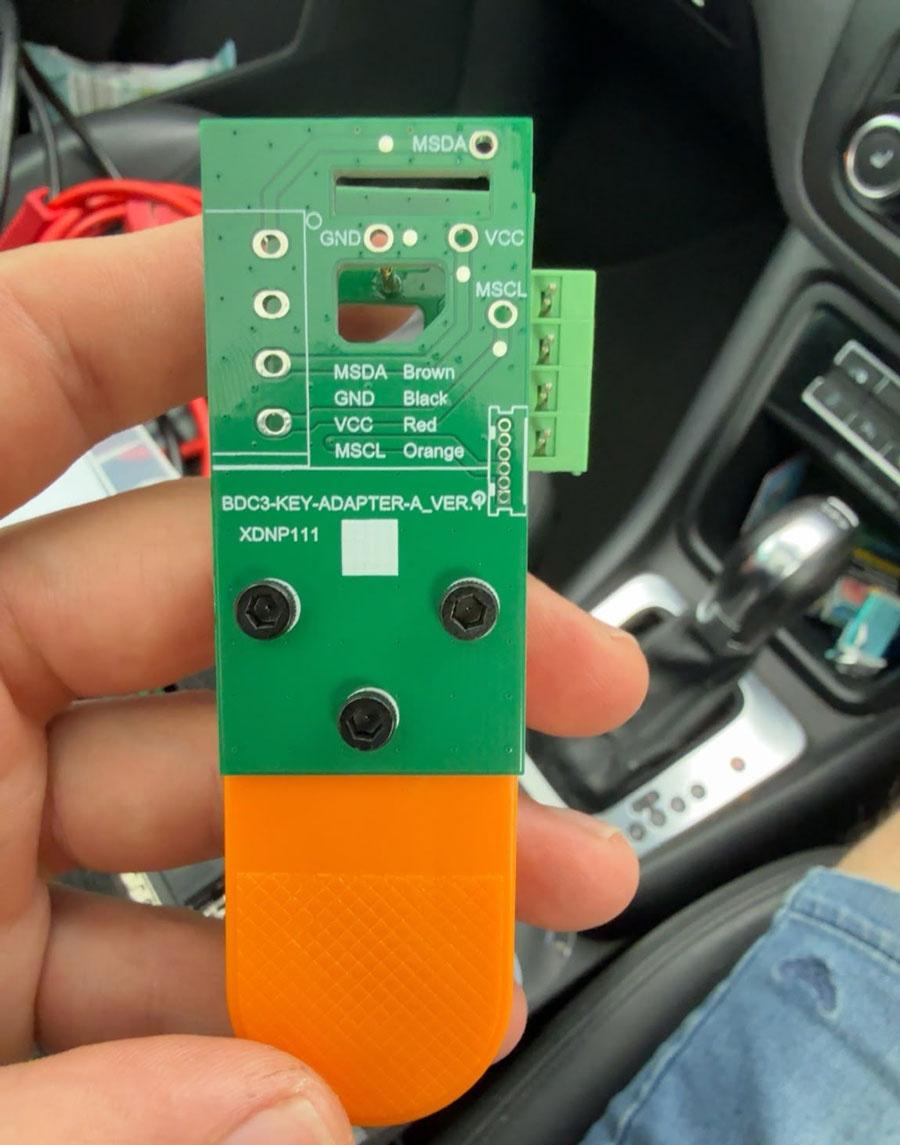
- The adapter indicated by KTP for the key being processed, such as XDNP111 BMW BDC03-D;
- Xhorse DB15/MCU cable;
- A supported original BMW key.
About the MCU Cable
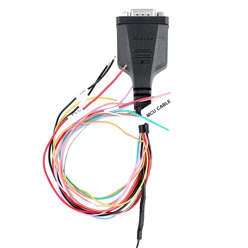
The MCU cable is included with some higher-version or advanced-configuration Xhorse devices. If it is not included in your package, please contact our sales team to purchase it separately.
Before ordering, send us the exact model or serial number of your Xhorse device so that we can confirm the correct cable and stock.
Step 1: Select the Key Type on VVDI Key Tool Plus
Turn on KTP and enter the BMW key-cloning function shown in the official tutorial. Select the correct key type.
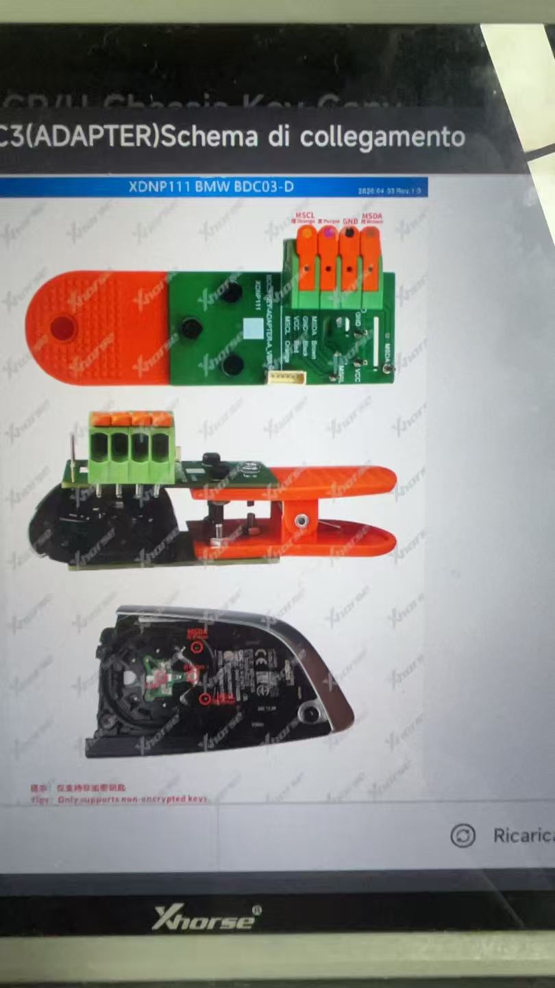
KTP will display:
- The adapter required for the operation;
- The adapter terminal names;
- The test points where the clamp must contact the key PCB.
For example
Here is the clue.
First of all, connect the XDNP11 clip with origianl BDC3 key.
Align the MSDA and MSCL pins on the adapter with the two points on the key PCB.
Clamp it in place and the installation is complete.
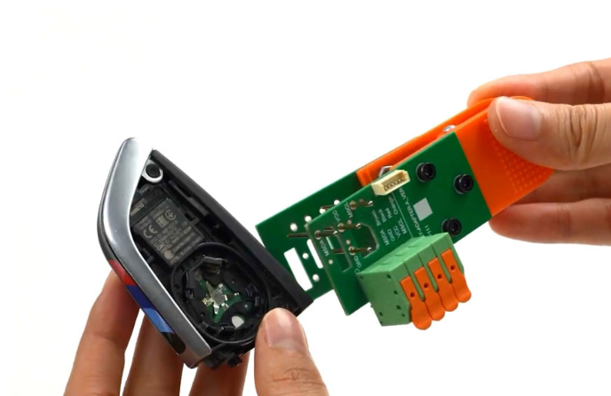
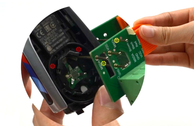
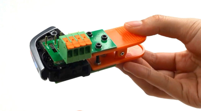
In Xhorse key tool plus, choose BMW BDC3 key reading (adapter) option. Device will show you the connection diagram.
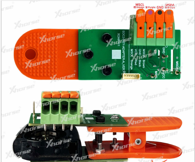
Connect the XDNP11 clip adapter with key tool plus via MCU cable according the pinout.
Orange-MSCLPurple/Red-VCCBlack-GNDBrown- MSDA
Flip the orange latch up, insert the MCU wiring harness, then press the orange latch down to lock it in place; clip the adapter onto the key.
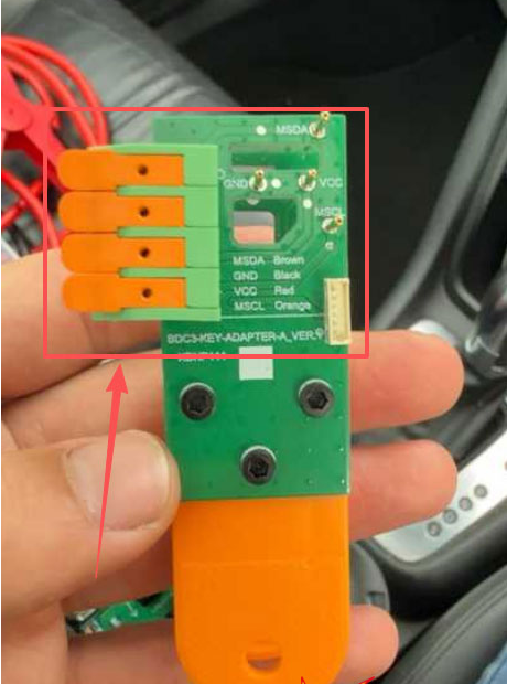
The screen may request XDNP111 BMW BDC03-D. Always use the adapter shown on your own KTP screen because another BMW key version may require a different adapter.
Step 2: Connect the DB15 End to KTP
Connect the DB15 end of the cable to the DB15 port on VVDI Key Tool Plus.
Check the connector orientation before inserting it. Push it in fully, but do not force it.
Step 3: Connect the MCU Wires to the Adapter
The loose wires on the MCU cable must be inserted into the corresponding green terminals on the selected adapter.
- Check the terminal names shown in the KTP connection diagram.
- Identify the matching labels on the MCU wires.
- Open the orange lever for the required terminal.
- Insert the correct MCU wire fully into the terminal.
- Close the orange lever to secure the wire.
- Repeat for every wire requested by KTP.
The screen may show signal points such as power, ground and communication lines. Connect each wire according to its signal label and terminal position.
Important: Do not connect the wires by color alone. The color layout can vary. Follow the wiring diagram displayed on KTP and the labels on the MCU cable.
Do not leave exposed wire strands outside the terminal, and make sure that two wires cannot touch each other.
Step 4: Install the Adapter on the Clamp
Fit the selected adapter board onto the orange XDNPBDGL clamp.
Make sure that:
- The adapter is facing the correct direction;
- The board is fully seated;
- The adapter does not move when the clamp is opened or closed;
- The probe pins are clean and straight.
Do not apply excessive force to the adapter board.
Step 5: Position the Clamp on the Original Key
Open the original BMW key housing and expose the PCB when required by KTP.
Use the diagram on the KTP screen to find the marked contact points on the key PCB. Position the clamp so that each probe pin contacts the correct point.
Then close the clamp carefully and verify that:
- The key PCB is held securely;
- The pins are centered on the correct test points;
- The clamp is not tilted;
- No probe is touching a nearby component or incorrect pad.
If the clamp is slightly misaligned, KTP may fail to detect or read the key.
Step 6: Confirm the Complete Connection
Before starting the operation, check the setup in this order:
- DB15 connector is securely connected to KTP.
- All required MCU wires are inserted into the correct adapter terminals.
- The correct XDNPBDGL adapter is fitted to the clamp.
- The clamp probes are aligned with the test points shown on KTP.
- The original key PCB is stable and cannot move.
- KTP has sufficient battery power or a stable power supply.
Step 7: Start Reading the Key with KTP
Return to the operation screen on VVDI Key Tool Plus and continue according to the on-screen instructions.
KTP will normally begin by detecting or reading the original key. Keep the clamp, cable and key completely still during the reading process.
If the key is detected successfully, continue with the key-cloning procedure shown by KTP and the official Xhorse video.
Do not remove the clamp or disconnect any wire while KTP is reading or writing data.
If KTP Cannot Detect the Key
If KTP reports a connection or reading error, stop the operation and check the following:
Check the adapter
Confirm that the adapter reference installed on the clamp is the same as the one displayed on KTP.
Check the MCU wires
Make sure every wire is in the correct terminal and is held securely by the orange lever. Verify the signal labels instead of relying only on wire colors.
Check the clamp position
Open the clamp and realign the probes with the test points on the key PCB. Even a small offset can prevent communication.
Check the probe contact
Clean dirty contact points carefully and confirm that all required probes touch the PCB evenly.
Check the KTP connection
Reconnect the DB15 plug and make sure KTP has stable power.
Do not start a write operation until the original key can be read reliably.
Frequently Asked Questions
Which cable connects KTP to the XDNPBDGL clamp?
Use the Xhorse DB15/MCU cable. The DB15 end connects to VVDI Key Tool Plus, while the required MCU wires connect to the corresponding terminals on the adapter fitted to the clamp.
Is the MCU cable included?
Some advanced or higher-configuration Xhorse devices include it. If your package does not contain the MCU cable, contact our sales team to order it separately.
Where do I insert the MCU wires?
Insert them into the green terminal block on the adapter. Open the orange lever, insert the wire into the terminal specified by KTP, and close the lever to lock it.
Can I copy the wire colors shown in another photo?
No. Use the signal labels and the live wiring diagram displayed on your own KTP. Different cable or hardware versions may use different colors.
Why does KTP not read the key after everything is connected?
The most common causes are the wrong adapter, a wire in the wrong terminal, a loose MCU wire or misaligned clamp probes. Recheck the full connection before trying again.
Quick Connection Summary
- Select the BMW key type on VVDI Key Tool Plus.
- Install the adapter specified by KTP on the clamp.
- Connect the DB15 end of the MCU cable to KTP.
- Insert the labeled MCU wires into the matching adapter terminals.
- Position the clamp probes on the original key PCB as shown on KTP.
- Confirm all connections and start the reading procedure.
Need the MCU cable?
Contact our sales team with your Xhorse device model or serial number. We will check whether your version should include it and help you purchase the correct cable if required.